- 您现在的位置:买卖IC网 > Sheet目录1215 > EVDP610 (IXYS)BOARD EVALUATION IXDP610
�� �
�
�EVDP610�
�up� to� 390KHz� (in� 7-bit� resolution).� The� external� clock� can�
�be� installed� into� the� via� on� the� board� labeled� TP3.�
�3.0� GUI� GENERAL� DESCRIPTION� AND� USE�
�3.1� The� GUI�
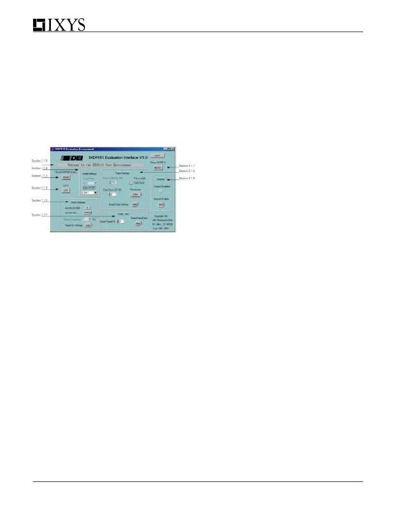
�After� installing� and� starting� up� the� GUI,� figure� 7� is� the� first�
�screen� that� should� appear.� The� Message� box� should�
�read:� “Welcome� to� the� IXDP610� Test� Environment”� as�
�seen� in� Figure� 6.� Be� aware� that� when� the� GUI� has�
�established� communication� with� the� evaluation� board,� the�
�GUI� will� reset� the� EVDP610� hardware� to� ensure� that� both�
�the� software� and� the� hardware� are� in� the� same� state.�
�Figure� 6:� The� EVDP610� GUI� GUI�
�3.1.1� Reset� IXDP610�
�This� toggle� button� will� reset� the� EVDP610� board� and� the�
�GUI� back� into� their� initial� states.� If� the� EVDP610�
�board’s� power� has� been� cycled� this� button� can� be� used�
�to� reset� the� GUI� software.� If� for� any� reason� the� hardware�
�and� software� disagree� this� button� can� be� used� to�
�reinitialize� the� hardware� and� the� software� into� the� same�
�state� (the� user� will� lose� the� current� settings� of� the�
�board).�
�3.1.2� Read� IXDP610� Status�
�This� toggle� button� will� read� the� status� of� the� EVDP610�
�board.� It� will� update� the� GUI� to� the� current� Pulse� Set-�
�tings,� Dead� Time� Settings,� Lock� Settings,� and� Output�
�Settings.� If� for� any� reason� the� hardware� and� software�
�disagree� this� button� can� be� used� to� read� what� the�
�hardware� is� doing� and� update� the� software.�
�3.1.3� Lock�
�This� button� will� “lock”� the� control� register� of� the� IXDP610,�
�which� will� not� allow� the� dead-time� period,� clock� divide,�
�resolution� or� the� stop� bit� to� be� changed.� Hitting� this�
�button� again,� or� hitting� the� RESET� IXDP610� button� will�
�unlock� the� IXDP610.�
�4�
�3.1.4� Serial� Settings�
�These� buttons� control� the� baud� rate� and� the� COM� port�
�selection� (1� –� 4).� *Note:� Baud� rate� is� not� variable� and�
�will� remain� dimmed.�
�3.1.5� Clock� Settings�
�The� CLOCK� DIVIDE� button� will� cause� the� input� clock� of�
�the� IXDP610� chip� to� be� internally� divided� by� 1� or� by� 2.�
�The� clock� select� button� allows� the� microprocessor� to�
�control� the� input� clock� to� the� IXDP610,� which� can� then�
�be� variably� changed� by� the� GUI.� The� output� frequency�
�ring� allows� the� user� to� select� the� frequency� of� the� output�
�of� the� IXDP610� from� 1� –� 50� Hz.� When� the� clock� is�
�selected� the� GUI� will� prompt� the� user� to� make� sure� of�
�the� correct� jumper� settings.�
�3.1.6� Pulse� Settings�
�The� Resolution� toggle� button� allows� the� user� to� switch�
�between� seven-bit� and� eight-bit� resolution� on� the�
�EVDP610� board.� The� pulse� width� can� be� written� to� the�
�IXDP610� by� either� the� Duty� Cycle� or� Pulse� Width.� One�
�of� these� must� be� selected� by� the� toggle� switch.� When�
�Duty� Cycle� is� selected� and� the� user� has� entered� a�
�number� into� the� Duty� Cycle� textbox� the� pulse� width�
�textbox� will� be� updated� with� the� actual� number� written�
�into� the� pulse� width� latch� of� the� IXDP610.� Duty� Cycle�
�and� Pulse� Width� are� always� calculated� with� respect� to�
�resolution,� meaning� if� the� value� entered� into� Duty� Cycle�
�was� 50%,� in� 7-bit� mode� the� pulse� width� number� will� be�
�64� where� as� in� 8-bit� resolution� the� pulse� width� number�
�will� be� 128.� The� pulse� width� text� box� will� display� the�
�actual� number� written� to� the� pulse� width� latch,� whereas�
�the� duty� cycle� is� calculated� based� on� the� entered�
�values.� Be� aware� that� if� you� were� to� enter� 128� in� the�
�pulse� width� textbox,� in� 8-bit� resolution,� the� output� duty�
�cycle� will� be� 50%.� If� the� IXDP610� is� switched� into� 7-bit�
�resolution� the� pulse� width� number� will� remain� the� same,�
�yet� the� duty� cycle� now� becomes� 100%� and� the� GUI� and�
�the� hardware� will� be� updated� with� these� values.�
�When� the� Read� Pulse� Settings� button� is� pressed� the�
�evaluation� board� updates� all� pulse� settings� in� the� area.�
�3.1.7� Dead� Time�
�Dead� Time� can� either� be� entered� manually� or� with� the�
�arrow� buttons� to� the� side� of� the� test� box.� The� Read�
�Dead� Time� button� updates� the� GUI� from� the� evaluation�
�board.� For� a� detailed� discussion� on� dead� time� please�
�see� section� 2.2.1� or� the� IXDP610� specification.�
�3.1.8� Outputs� Enable�
�The� Outputs� Enable� button� allows� the� user� to� turn� on/off�
�the� outputs� of� the� IXDP610.� This� button� asserts� the� stop�
�bit� in� the� control� latch� of� the� IXDP610.� When� the� out-�
�puts� are� enabled� the� status� LED� located� directly� above�
�the� button� will� light.� The� LED� will� turn� off� when� the�
�发布紧急采购,3分钟左右您将得到回复。
相关PDF资料
EYP-2MT098B
THERMAL CUTOFF 98C 2A/50VDC TAB
EZ3-A230XF1
SURGE ARRESTER 230V GASTUBE 3PIN
EZJ-Z1V39010
VARISTOR MULTILAYER 39V 0603
EZN-4100LCMUS-2
KEYBOARD EZCLEAN 83 KEYS USB
F0402G0R20FNTR
FUSE 0.20A 32V FAST THIN 0402
F1206A2R00FWTR\500
FUSE 2.00A 32V FAST THIN 1206
F1206B1R50FWTR
FUSE 1.50A 63V FAST THIN 1206
F200-003-R
CARD IEEE1394 FIREWIRE PCI
相关代理商/技术参数
EVDS430SI
功能描述:电源管理IC开发工具 30A Ultra Fast MOSFET/IGBT Driver RoHS:否 制造商:Maxim Integrated 产品:Evaluation Kits 类型:Battery Management 工具用于评估:MAX17710GB 输入电压: 输出电压:1.8 V
EVDXXXX
制造商:未知厂家 制造商全称:未知厂家 功能描述:MILITARY QUALITY REMOVABLE CONTACT, SUBMINIATURE-D CONNECTORS
EVE2-29A-BLM-TPN
功能描述:DISPLAY LCD TFT TOUCH RES 2.9" E 制造商:matrix orbital 系列:- 零件状态:在售 显示类型:TFT - 彩色 显示模式:可传导的 触摸屏:- 屏幕对角线尺寸:2.9"(73.66mm) 可视范围:72.10mm 宽 x 26.10mm 高 背光:- 点像素:320 x 102 接口:SPI 图形颜色:红色,绿色,蓝色(RGB) 背景颜色:黑色 点尺寸:- 点间距:- 标准包装:1
EVE2-35A-BLM-TPN
功能描述:DISPLAY LCD TFT 3.5" EVE 制造商:matrix orbital 系列:- 零件状态:在售 显示类型:TFT - 彩色 显示模式:可传导的 触摸屏:- 屏幕对角线尺寸:3.5"(88.90mm) 可视范围:73.10mm 宽 x 55.50mm 高 背光:- 点像素:320 x 240 接口:SPI 图形颜色:红色,绿色,蓝色(RGB) 背景颜色:黑色 点尺寸:- 点间距:- 标准包装:1
EVE2-35A-BLM-TPR
功能描述:DISPLAY LCD TFT TOUCH RES 3.5" E 制造商:matrix orbital 系列:- 零件状态:在售 显示类型:TFT - 彩色 显示模式:可传导的 触摸屏:电阻 屏幕对角线尺寸:3.5"(88.90mm) 可视范围:72.28mm 宽 x 54.76mm 高 背光:- 点像素:320 x 240 接口:SPI 图形颜色:红色,绿色,蓝色(RGB) 背景颜色:黑色 点尺寸:- 点间距:- 标准包装:1
EVE2-38A-BLH-TPR
功能描述:DISPLAY LCD TFT TOUCH RES 3.8" E 制造商:matrix orbital 系列:- 零件状态:在售 显示类型:TFT - 彩色 显示模式:可传导的 触摸屏:电阻 屏幕对角线尺寸:3.8"(96.52mm) 可视范围:96.84mm 宽 x 25.10mm 高 背光:- 点像素:480 x 116 接口:SPI 图形颜色:红色,绿色,蓝色(RGB) 背景颜色:黑色 点尺寸:- 点间距:- 标准包装:1
EVE2-43A-BLM-TPN
功能描述:DISPLAY LCD TFT 4.3" EVE 制造商:matrix orbital 系列:- 零件状态:在售 显示类型:TFT - 彩色 显示模式:可传导的 触摸屏:- 屏幕对角线尺寸:4.3"(109.22mm) 可视范围:98.70mm 宽 x 57.50mm 高 背光:- 点像素:480 x 272 接口:SPI 图形颜色:红色,绿色,蓝色(RGB) 背景颜色:黑色 点尺寸:- 点间距:- 标准包装:1
EVE2-43A-BLM-TPR
功能描述:DISPLAY LCD TFT TOUCH RES 4.3" E 制造商:matrix orbital 系列:- 零件状态:在售 显示类型:TFT - 彩色 显示模式:可传导的 触摸屏:电阻 屏幕对角线尺寸:4.3"(109.22mm) 可视范围:97.04mm 宽 x 55.85mm 高 背光:- 点像素:480 x 272 接口:SPI 图形颜色:红色,绿色,蓝色(RGB) 背景颜色:黑色 点尺寸:- 点间距:- 标准包装:1